PIC32MX230F064BでchipKITクローンを作る
How to make chipKIT clone for PIC32MX230F064B
前回では、PIC32MX250F128BでchipKITクローンを作成し、Arduino IDEから開発する手法を紹介しました。記録領域の関係で、USBブートローダーを書き込めるのはPIC32MX250F128BもしくはPIC32MX270F256Bに限られるのですが、データ量の少ないUARTブートローダーであれば、より安価なPIC32MX230F064BマイコンでもArduino開発が行えます。
まずは、カスタマイズしたブートローダーを用意します。Githubにある「
PIC32-avrdude-bootloader」リポジトリをクローンし、MPLAB IDEなどで開きます。環境を整えるの場面倒くさい方はビルド済みバイナリを私の
Githubリポジトリにアップロードしているので、こちらを直接ダウンロードしてください。
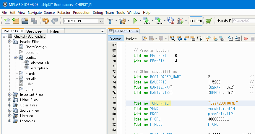
ビルドリストから「CHIPKIT_PI」を選択し、「[Header]/configs/element14.h」ファイルを開き、以下のようにコードを書き換えます。この状態で、RB0,RB1ピンがUART、RB2がブートローダーモードLED、RB4がブートローダー起動ボタンになります。
element14.h
/* Element 14 Boards */

#define     prodChipkitPi		0x0001

//************************************************************************
#if defined(_BOARD_CHIPKIT_PI_)   // UART (Default) version
#define _CONFIG_VALID_
// NOTE: As of 8/20/2013 the crystal on the board (v3.37 and above) is now 8MHz, so this bootloader has been updated

#if defined(PUT_CONFIG_BITS_HERE)

    //* Oscillator Settings
    #pragma config FNOSC    = PRIPLL                                // Oscillator selection
    #pragma config POSCMOD  = XT                                    // Primary oscillator mode
    #pragma config FPLLIDIV = DIV_2                                 // PLL input divider
    #pragma config FPLLMUL  = MUL_20                                // PLL multiplier
    #pragma config FPLLODIV = DIV_2                                 // PLL output divider
    #pragma config FPBDIV   = DIV_1                                 // Peripheral bus clock divider
    #pragma config FSOSCEN  = OFF                                   // Secondary oscillator enable

    //* Clock control settings
    #pragma config IESO     = OFF                                   // Internal/external clock switchover
    #pragma config FCKSM    = CSECME                                // Clock switching (CSx)/Clock monitor (CMx)
    #pragma config OSCIOFNC = OFF                                   // Clock output on OSCO pin enable

    //* USB Settings
    #pragma config UPLLEN   = ON                                    // USB PLL enable
    #pragma config UPLLIDIV = DIV_2                                 // USB PLL input divider
    #pragma config FUSBIDIO = OFF									// USB USID pin controlled by port function
    #pragma config FVBUSONIO = OFF									// USB VBUSON pin controlled by port function

    //* Other Peripheral Device settings
    #pragma config FWDTEN   = OFF                                   // Watchdog timer enable
    #pragma config WDTPS    = PS1024                                // Watchdog timer postscaler
    #pragma config WINDIS   = OFF
    #pragma config JTAGEN   = OFF                          			// JTAG port disabled

    //* Code Protection settings
    #pragma config CP       = OFF                                   // Code protection
    #pragma config BWP      = OFF                                   // Boot flash write protect
    #pragma config PWP      = OFF                                   // Program flash write protect

    //*    Debug settings
    #pragma config ICESEL   = ICS_PGx1                      		// ICE/ICD Comm Channel Select
    //#pragma config DEBUG    = ON                          		// DO NOT SET THIS CONFIG BIT, it will break debugging

    #pragma config PMDL1WAY = OFF                           		// Allow multiple reconfigurations
    #pragma config IOL1WAY  = OFF                           		// Allow multiple reconfigurations
#endif

	// LED1 on RA0
	// LED2 on RB15
	// Boot button on RB9
    #define CAPABILITIES    (blCapBootLED | blCapUARTInterface | blCapProgramButton | blCapVirtualProgramButton | CAPCOMMON)

    // BTN / LED sense
    #define LedOn       High
    #define BntOn       Low

    // Boot LED
    #define BLedLat     B
    #define BLedBit     2

    // Virtual program button
    #define VPBntLat    B
    #define VPBntBit    4

    // Program button
    #define PBntPort    B
    #define PBntBit     4

    // Other capabilities
    #define BOOTLOADER_UART             2                   // avrdude program UART
    #define BAUDRATE                    115200              // avrdude baudrate
    #define UARTMapRX()                 (U2RXR = 0x2)       // RB1 -> U2RX
    #define UARTMapTX()                 (RPB0R = 0x2)       // RB0 -> U2TX

    #define _CPU_NAME_                  "32MX230F064B"
    #define VEND                        vendElement14
    #define PROD                        prodChipkitPi
    #define F_CPU                       40000000UL
    #define F_PBUS                      F_CPU

    #define FLASH_BYTES                 0x8000		    // 32K
    #define FLASH_PAGE_SIZE             1024						// In bytes
#endif
手持ちのコンパイラが対応しているようであれば、最適化のオプションに「s(サイズ優先)」を選び、hexファイルを作成します。ここからは、前回と同じ手順でブートローダーをマイコンに書き込みます。
ブートローダーモードになったことを確認したら、Arduino IDEからinoファイルを書き込んでみましょう。書き込みには
USBシリアル変換アダプタなどのシリアル通信機器が必要で、このTX/RX端子をPICマイコンのRB0/RB1端子に接続し、機器の保有するCOMポートをArduino IDEから指定することで、プログラムの書き込みが可能になります。
2020/01/12